Rotary Motors for Precision Positioning – What to Choose When?
Part One: DC Motors, Brushless Motors, and Torque Motors
1 Electrodynamic Rotary Motors for Precision Positioning
Rotary motors have been around for almost 200 years. According to Wikipedia “The first commutator DC electric motor capable of turning machinery was invented by British scientist William Sturgeon in 1832.” Over the years, electric motors have been continuously improved, driving the industrial revolution. The largest market segment for electric motors is in industrial and domestic mechanical power generation, driving machinery, and auxiliary equipment such as pumps and fans etc. Electric motors have also become a mainstay of the precision automation and positioning industry. They are usually smaller than industrial motors and have to meet different requirements.
Today, there are many variations of the original DC motor. Progress in electronic motion control has made stepper motors and brushless DC motors (BLDC) possible, and the use of rare earth magnets has helped to reduce their size while increasing their torque output significantly. In positioning systems, motion is required in linear form more often than not, so rotary motors are coupled with lead screws or ball screws to convert the motor's basic rotary output into linear translation. Of course, there are also a number of motors producing linear output directly, which are discussed here and here.
Most precision positioning stages are still driven by rotary motors for reasons such as size, cost, holding force, and controllability. Among the various designs of electric rotary motors used in precision positioning applications, each have different strengths and limitations which will be discussed in this white paper. In addition to electrodynamic (electromagnetic) motors, non-magnetic motors such as piezoelectric linear and rotary motors have recently been adopted by precision motion engineers for unique features such as small size, high precision, low heat generation and self-locking capabilities. More information on these types of electro-ceramic motors can be found here.
2 Direct Current Motor (DC)
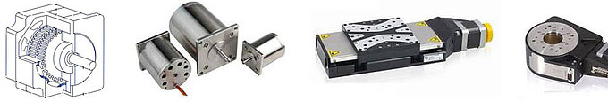
DC motors are compact and provide smooth and vibration-free motion along with good dynamics over a large range of speeds (0 to several 1000 rpm). They are easy to control – a change in the DC drive voltage is proportional to the motor velocity. Because of the need for brushes and mechanical contact to provide electrical power to the rotor, their lifetime is primarily dependent on the wear of the brushes which typically last 1,000 to 5,000 hours. This is sufficient for most precision motion applications in instrumentation and lab environments; however, for 24/7 applications in the industrial market, there may be better solutions. For linear positioning applications, a motor running 3000 rpm (50/sec) driving a screw with a pitch of 1mm/revolution provides linear motion with a travel velocity of 50mm/sec. DC motors can be used in vacuum applications but only to pressures down to 10-6 hPa, because the brushes need a minimum humidity level to work. With the wear of the brushes, carbon dust is generated which must be considered for clean rooms and optical applications.
Torque Amplifiers:
Small DC motors provide high speed up to 10000 rpm and more at the expense of torque. For positioning applications often a gearbox needs to be added to provide the required torque to overcome the friction of a lead screw or provide enough push/pull or holding force.
2.1 How it works
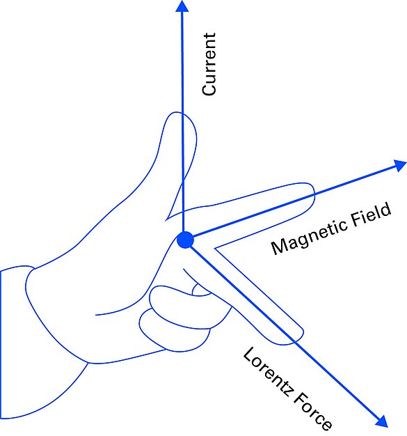
A DC motor exploits the force effect of an electrical current in a conductor loop in a magnetic field. The movement is caused by the Lorentz force, resulting from the charge carriers in the electromagnetic field. The right-hand-rule (figure 1) establishes the direction of the force relative to the direction of the current and the magnetic field.
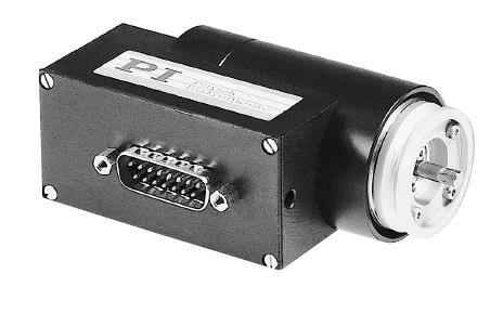
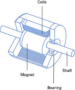
For compact positioning devices, PI employs DC motors with permanent magnets (stator) and moving coils (rotor) energized through brushes.
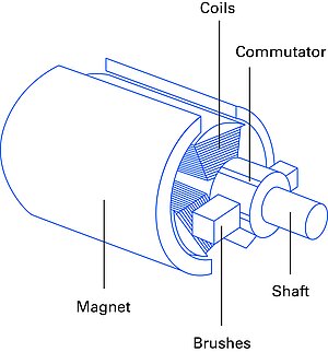
In order for the motor to perform a revolution, the polarity of the applied direct current needs to be alternated (switched). This is achieved with a commutator, in its most basic version, a segmented slip ring. As the magnetic force turns the rotor, the static carbon brushes make contact with different segments on the commutator, connected the rotor windings, resulting in an alternating current required to maintain the direction of force with continued movement. Figure 2a shows an example of a permanent DC motor design.
2.2 Operating Behavior
The basic equivalent electric circuit of a simple DC motor can be reduced to the following diagram (fig 3)
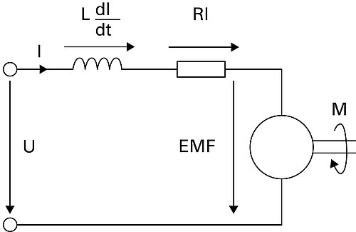
This results in a motor voltage according to the law of induction: V = LdIdt+RI+EMF
L is the winding inductance, I the motor current, R the winding resistance, and EMF is the induced voltage counteracting the motion. This is described as the back electromotive force (back-EMF). This force acts proportional to the rotational speed. When the back-EMF equals the motor voltage, the maximum rotational speed will be achieved. In DC motors, the voltage drop over the inductance can be neglected, resulting in a proportionality of voltage and rotational speed where the sign of the voltage determines the direction of rotation:
V = RI+kΦ2πn
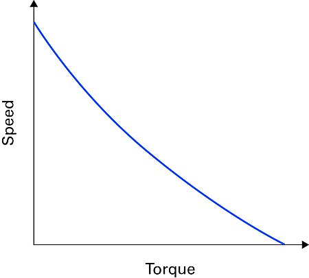
k is the motor constant, Φ is the magnetic flux in the air gap, and n is the rotational speed. Accordingly, the produced torque M = kΦI is proportional to the motor current. A combination of both equations results in a decrease of the rotational speed under load that is proportional to the torque. Fig. 4 shows the resulting torque/speed characteristics.
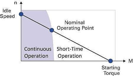
2.2.1 Continuous Operation – Average Output
DC motors can provide the highest torque output at 0 rpm (standstill) while torque output drops to zero at their top rpm. Between these extremes, the torque/speed curve characterizes the performance of a motor, and a flatter curve generally indicates a higher resistance to load changes and thus a more powerful motor. In order to maximize the life, torque (current) has to be limited to a safe range (continuous operation, specified by the manufacturer). Peak output needs to be limited for short periods of time. The intersection between continuous operation and short term operation with the torque/speed characteristic curve is the nominal operating point.
There are two ways to shift the curve up while maintaining the gradient (i.e. higher idle speed and higher starting torque): either thicker copper in the windings or a higher voltage during operation.
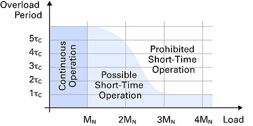
2.2.2 Short Time Operation – Limiting Factors for Peak Output
One of the limiting factors for short term peak output is maximum permissible winding temperature. Generally, the permissible time in the short term operation part of the curve is one to three seconds and is signified by the thermal time constant of the winding and the extent of the overload. Figure 5 shows an example of typical values. In addition to over temperature damage, excessive high currents could also irrevocably de-magnetize the permanent magnets. Mounting position, convection, ambient pressure (vacuum), etc. may also pose limitations.
Higher loads result in increased motor losses due to the proportionality of torque and current, leading to higher temperature losses and increased resistance.
As an estimate, the heat losses PL = RI2 can be multiplied by thermal resistance (based on the motor manufacturer’s data sheet). Should the motor be operated at its thermal limits, a closer examination is required. The motors are limited thermally by the surrounding temperature as well as maximum winding temperatures.
2.3 Use in Precision Position Control Applications
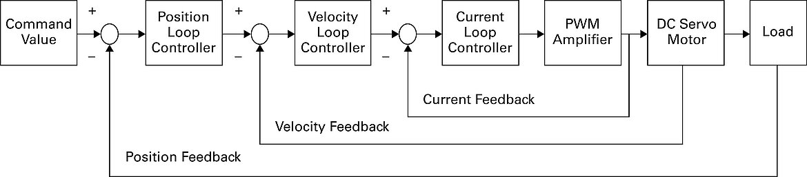
For precision motion and positioning applications, DC motors require position encoders, e.g., incremental or absolute encoders to provide feedback to a motion controller (closed loop operation). The higher the encoder resolution, the more precise position and velocity can be controlled. In addition, torque can be controlled by measuring the output current at the driver. Figure 6a shows an example of a closed loop. Both motor-shaft mounted rotary encoders (indirect metrology) and stage mounted encoders (direct metrology) can be used for feedback. Additional tachometers can be used to provide better velocity control if required.
2.3.1 Dual-Loop Controller
Dual loop controllers, such as those provided by ACS Motion Control, can derive position and velocity information from one encoder at the same time. Stage platform coupled direct encoders (i.e. a linear encoder on a linear stage or a high resolution rotary encoder on a rotary stage platform) usually provide better position accuracy than indirect measuring motor-shaft mounted rotary encoders. However, it can reduce the bandwidth of the velocity control loop because the stage mounted direct encoder registers the oscillations of the motion platform to a higher degree than the rotary encoder downstream on the motor shaft.
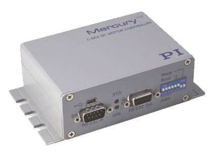
3 DC Motor with Integrated PWM Drive (ActiveDrive)
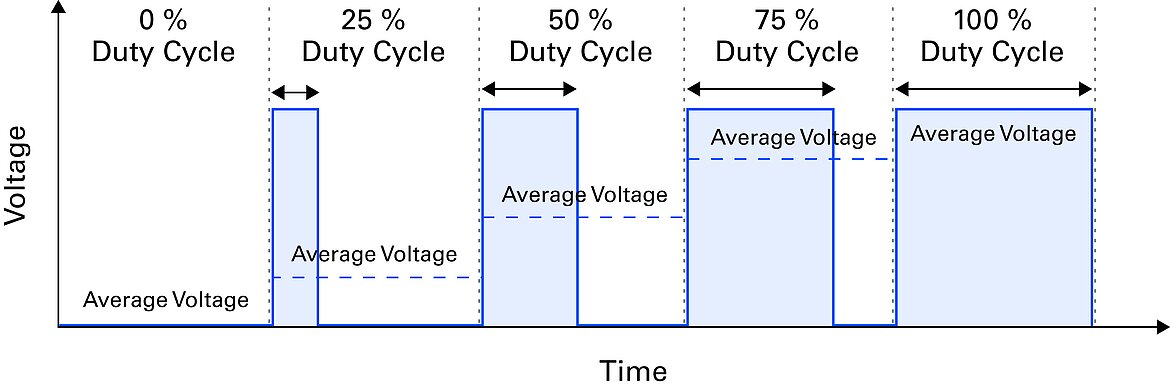
PI’s ActiveDrive technology eliminates the need to add a separate driver (power amplifier) to a motion controller. It simplifies scalability and allows the use of compact low powered controllers. With ActiveDrive, the PWM amplifier is integrated together with the motor in a shielded case and supplied with DC current directly through a stage mounted connector. The controller only needs to output low power pulse width modulation (PWM) signals making thin, flexible cables between controller and motor feasible. The low currents sent over the motor cables also limit the negative influence on sensitive instrumentation by electric noise. PWM amplifiers are smaller, more efficient, lower cost, and generate less heat than linear amplifiers – they vary output power by changing the ratio of on/off-duration, as shown in figure 7a.
4 Brushless DC Motor (BLDC) / Synchronous Servo Motor (SSVM)
4.1 Motor Design
Despite its name a Brushless Direct Current motor (BLDC) strongly differs from the design of a DC motor. Actually it is more related to a permanent-magnet synchronous motor which is whyBLDC motors are sometimes referred to as synchronous servo motors (SSVM), especially when used as low-voltage industrial motors. The term BLDC emphasizes the brushless commutation whereas the term SSVM stresses the rotor movement synchronous to the rotating magnetic field. Sometimes, a difference is made based on the control type (block or sinusoidal commutation); in this scenario, block commutation refers to a BLDC motor, and sinusoidal commutation to an SSVM – see fig. 8 for basic design.
Due to their brushless commutation, BLDCs provide many advantages compared to traditional brushed DC motors which makes them the preferred choice in industrial 24/7 applications.
- Increased lifetime, typically several 10,000 hours. Since there are no brushes to wear, the bearing design becomes the main limiting factor.
- Smaller size. The brushless design allows for a smaller, lighter, more efficient design, while providing the same performance; resulting in an improved torque/motor size ratio.
- The electronic commutation allows for high dynamics at low temperatures with few vibrations.
As opposed to traditional DC motors, where the coils are moving, in this design the windings are static and create a rotating magnetic field generated by a specific electronic circuit to drive the permanent magnet rotor; since the commutation is purely electronic this type of motor is also referred to as electronically commutated motor (EC motor). The rotor rotates synchronously to the alternating current of the stator winding and the rotational speed is determined by
n = f/p
The operational speed depends on the frequency f and the number of pole pairs p, determined by the motor design.
4.2 Operating Behavior
The operating behavior of a brushless DC motor is close to a traditional DC motor, explaining the origin of the name despite the deviating design but the speed/torque curve can show a somewhat nonlinear, load-dependent relation, as depicted in fig. 9.
4.3 Determination of the Rotor Position
For maximum torque, the stator and rotor magnetic fields need to be in synch and perpendicular to each other at all times. To keep the synchronization for different load and speed situations, the exact rotor position needs to be available to the controlling circuit. There are two ways to achieve that – a) by integrating additional Hall sensors, b) by measuring the back EMF. B) works best for continuous operation at high speed and requires a specific startup process because the EMF is too small at low speeds and disappears completely at standstill.
4.4 Block Commutation
Block commutation is a simple way of operating a BLDC motor. In case of a three-phase motor, with three hall sensors, offset by 120° to one another, the signal combinations define 6 rotor positions spaced at 60° intervals. The current between the phases is switched in blocks, i.e., in six steps of 60° for each revolution (fig 10 b) . The downside of this economical and simple method is that the magnetic stator field is static over 60° while the rotor field continues its revolution due to the turning permanent magnet. Consequently, the magnetic fields are not always perpendicular to each other. Placing hall sensors in the center of the two switchover points will result in a phase shift of 30° each, decreasing the torque by approximately 13.4%. These torque ripples occur at six times the electric rotation frequency of the motor, causing vibrations and noise (see fig 10b).
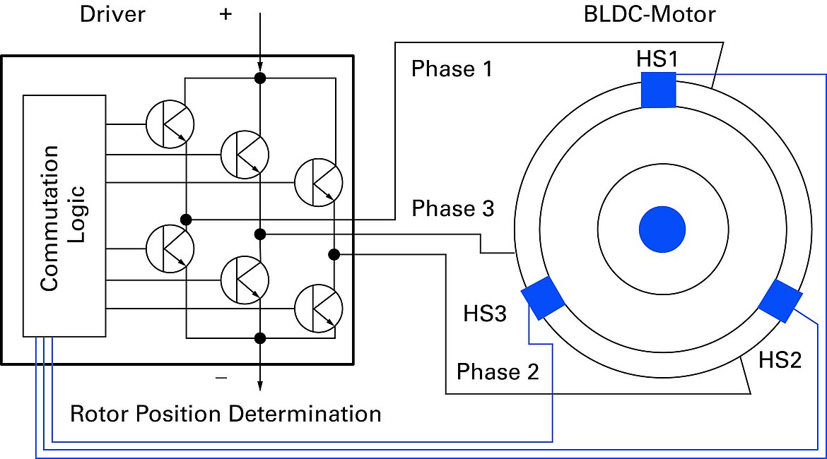
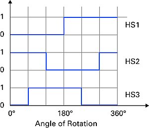
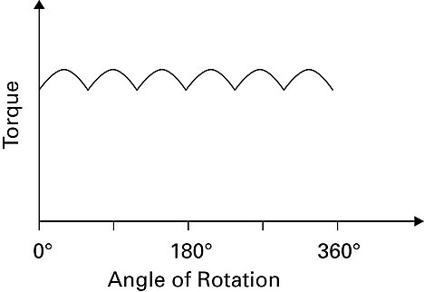
Fig. 10 (a) Block commutation principle on a BLDC motor
(b) Hall sensor signals HS1, HS2, and HS3
(c) torque ripple
4.5 Sinusoidal Commutation
Smoother motion can be achieved with sinusoidal commutation where the drive current is not a square wave but a sinusoidal signal phase-shifted by 120° between each motor winding. It is possible to interpolate the position signals from the hall sensors to provide more detailed position information of the rotor and avoid torque ripples, but for the best results an additional position encoder enables the controller to precisely control the current in each winding. In this scenario, hall sensors are redundant or may be used for the determination of the phases respectively. The described operation is available for PI's C-891 3-phase motion controllers, SMC Hydra controllers, as well as all ACS motion controllers.
4.6 Field-Oriented Control
At high rotor speeds, the calculated currents may lag behind the actual rotor position as a result of limited control bandwidth, which means that the stator and rotor field are no longer exactly perpendicular to each other. This can be avoided by field-oriented control, also called vector control, where the current vector is controlled in the rotating coordinate system of the rotor resulting in extended speed and positioning accuracy. This type of operation is available with the PI C-891 3-phase motion controller as well as all ACS Motion Controllers.
5 Torque Motor (TQM)
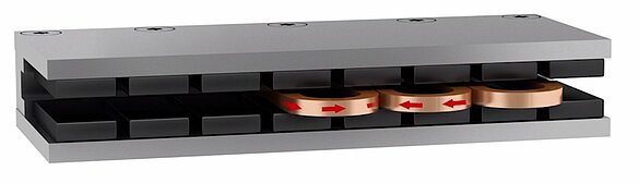
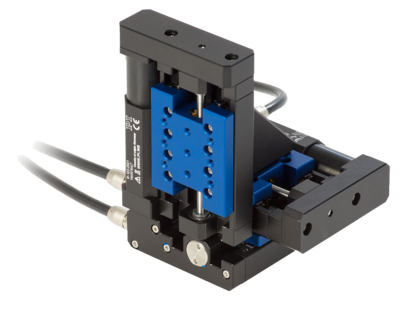
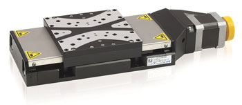
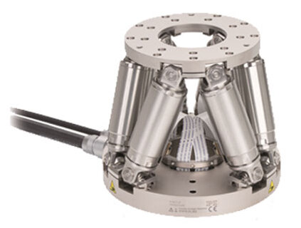
Torque motors are permanent-magnet synchronous rotary motors providing smooth motion, high peak and continuous torque, and high efficiency. They are used in applications where the load is directly connected to the rotor, without additional components such as gear boxes.A torque motor is similar to a linear motor bent into a circle or a low profile BLDC motor, with a large diameter (fig. 11a). In precision positioning applications, torque motors are often employed in rotary stages, directly driving the platform (turn table) without play or backlash.
The large radial dimensions allow for hollow shafts and large apertures, an advantage for conducting laser beams or cables. Because of the motor design, gear boxes are not required to amplify the torque output, eliminating backlash and play, leading to higher stiffness, positioning accuracy and repeatability. The direct drive principle also provides high dynamics, important for fast acceleration and step/settle response.
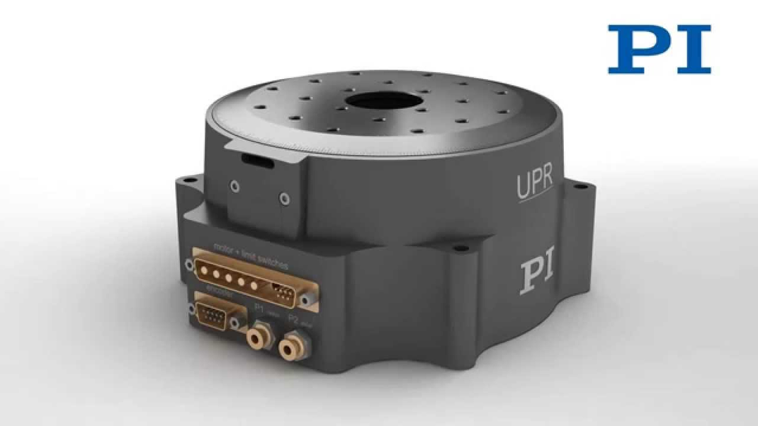
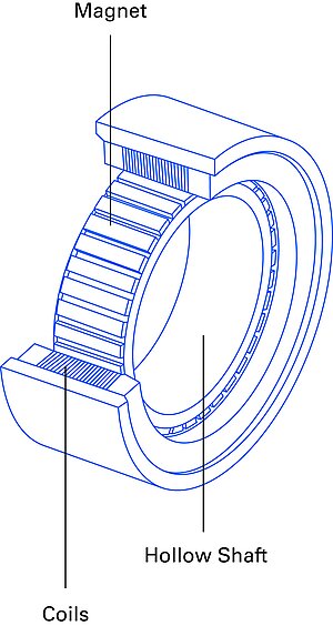
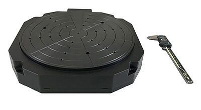
Fig 11b Low profile air bearing rotary stage driven by torque motors.
Due to the center-based hollow shaft, torque motors are sometimes referred to as hollow shaft motors. When coupled to a lead screw or ball screw running through the motor, particularly compact drive trains for linear stages or linear actuators can be designed, because the motor does not add to the length of the screw. The design of torque motors differs from BLDC motors with respect to the large number of pole pairs, accounting for high torques at medium and high speed.
The torque can be determined by: M ~ A⋅B⋅l⋅D2
With
A: current coverage in the stator winding,
B: flux density in the air gap,
I: active motor length
D: rotor diameter.
With its quadratic relationship, increasing the diameter is the easiest way to increase the torque. The coils can be applied in a three phase star connections, for enhanced torque output per unit current. For higher speed and lower operation voltage, delta connections are also possible.
Authors: Dr. Nico Bolse, Stefan Vorndran