C-887.3111 NEW!
6-axis controller for hexapods, integrated drivers for BLDC motors, TCP/IP, RS-232, 19" 2 RU housing, analog inputs


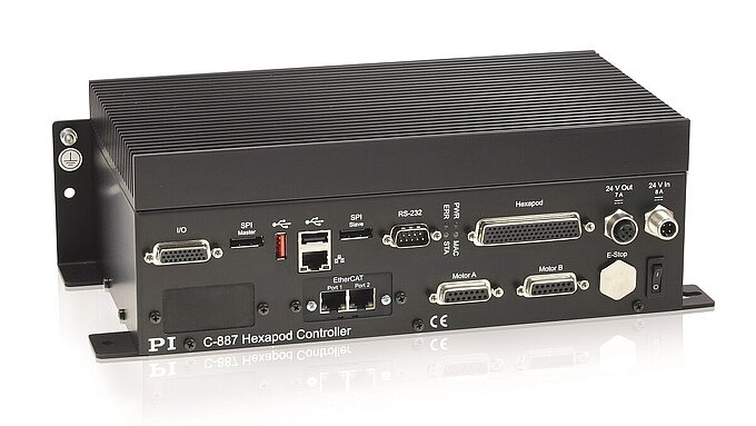
Hexapod controller for industrial use
Compact controller with integrated drivers for controlling hexapods for industrial applications. This controller is ideally suited for the operation of parallel kinematics that are equipped with BLDC motors and do not contain motor drivers. Hexapods with motor brakes and encoder connection via BiSS C are supported. Depending on the version and in combination with suitable hardware, the controller can meet the requirements of SIL 3 in accordance with EN IEC 62061 and thus guarantee a high level of functional safety for safety-related applications (certification still pending).
Operation
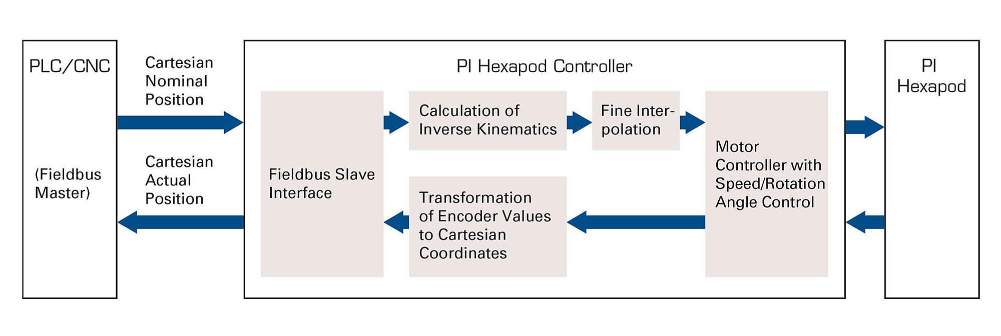
Operation of the hexapod system is simple and intuitive, as the position is entered in Cartesian coordinates. In each servo cycle, the controller calculates the control of the hexapod kinematics from the target positions entered. For customized integration of the hexapod system, the coordinate systems (Work, Tool) can be adapted by the user to the individual installation situation. The center of rotation can be freely defined in space. A data recorder can record operating data, e.g., motor control, velocity, position, or position error. The execution of macros and Python scripts on the controller enables standalone operation.
Interfaces
For use with the GCS 2.0 command set for PI positioning systems:
Depending on the version:
Extensive software assistance
For control via GCS-based interfaces. For example, PIMikroMove user software enables fast alignment routines to be depicted graphically. Extensive set of drivers, e.g., for use with C, C++, C#, NI LabVIEW, MATLAB, and Python. PIHexapodEmulator for virtual startup and operation without hardware.
Scope of delivery
The delivery includes the controller and a software package. A power adapter is not included in the scope of delivery. PI offers a 24 V power supply as an accessory (order number C-501.24250D3W3), which allows the controller to be operated as a laboratory device.
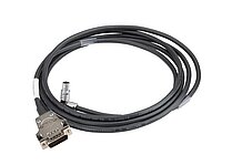
It is recommended to order the hexapod mechanics and a suitable hexapod cable set together with the controller so that the components can be matched before delivery. To be provided by the customer depending on the controller version:
| Basics | C-887.3111 | C-887.3511 | C-887.4101 | C-887.4111 | C-887.4511 | |
|---|---|---|---|---|---|---|
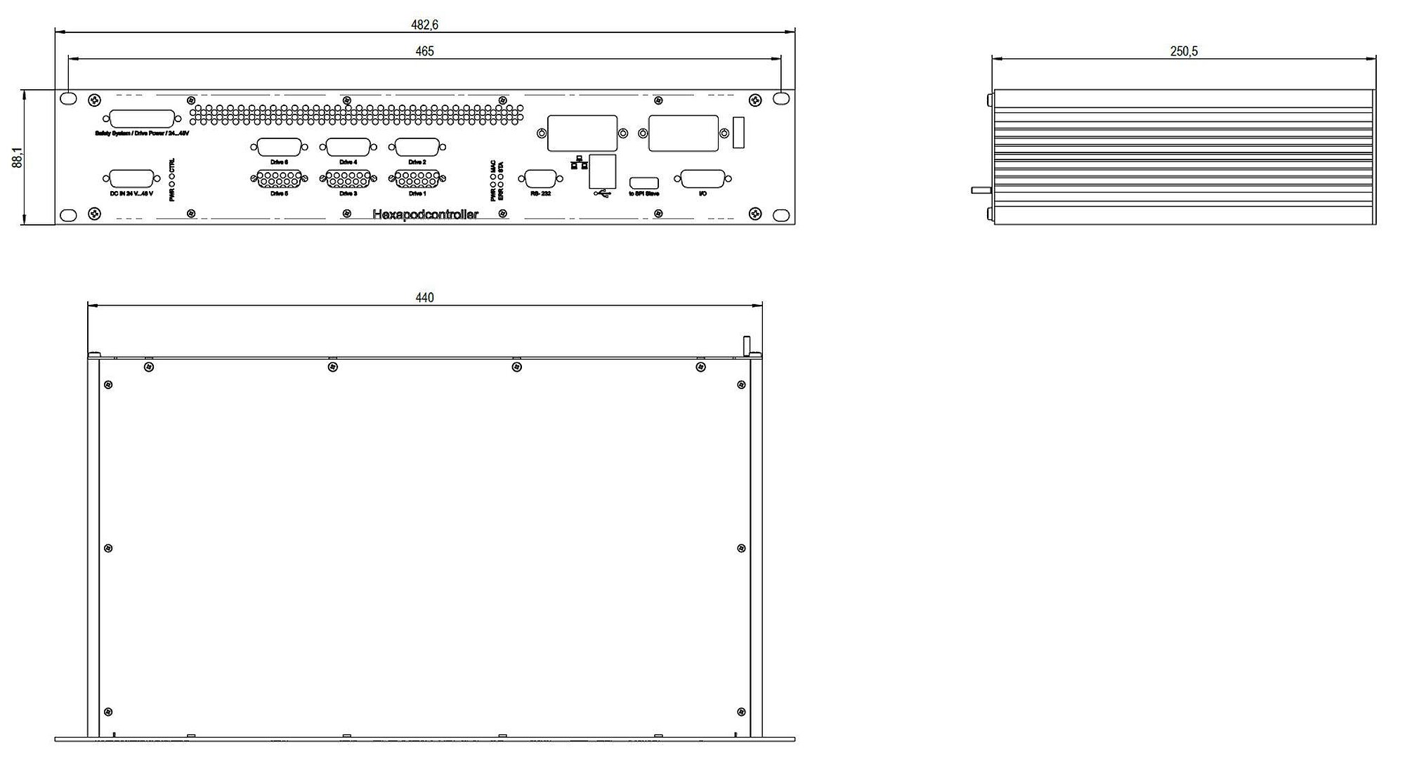
| Housing type | Rack-mount 19" 2 RU | Rack-mount 19" 2 RU | Rack-mount 19" 2 RU | Rack-mount 19" 2 RU | Rack-mount 19" 2 RU | |
| Drive type | Brushless DC motor ǀ Brushless DC gear motor | Brushless DC motor ǀ Brushless DC gear motor | Brushless DC motor ǀ Brushless DC gear motor | Brushless DC motor ǀ Brushless DC gear motor | Brushless DC motor ǀ Brushless DC gear motor | |
| Axes | 6 | 6 | 6 | 6 | 6 | |
| Processor | Intel Atom Dual Core (1.8 GHz) | Intel Atom Dual Core (1.8 GHz) | Intel Atom Dual Core (1.8 GHz) | Intel Atom Dual Core (1.8 GHz) | Intel Atom Dual Core (1.8 GHz) | |
| Application-related functions | Controller macros GCS ǀ Controller macros PIPython ǀ Startup macro ǀ Data recorder ǀ Fast Alignment | Controller macros GCS ǀ Controller macros PIPython ǀ Startup macro ǀ Data recorder ǀ Fast Alignment | Controller macros GCS ǀ Controller macros PIPython ǀ Startup macro ǀ Data recorder ǀ Fast Alignment | Controller macros GCS ǀ Controller macros PIPython ǀ Startup macro ǀ Data recorder ǀ Fast Alignment | Controller macros GCS ǀ Controller macros PIPython ǀ Startup macro ǀ Data recorder ǀ Fast Alignment | |
| Protective functions | Switch-off of the servo mode in case of an error ǀ Overheat protection of the motor | Switch-off of the servo mode in case of an error ǀ Overheat protection of the motor | Switch-off of the servo mode in case of an error ǀ Overheat protection of the motor | Switch-off of the servo mode in case of an error ǀ Overheat protection of the motor | Switch-off of the servo mode in case of an error ǀ Overheat protection of the motor | |
| Functional safety | — | — | STO (Safe Torque Off) ǀ SS1-t (Safe Stop 1 time controlled) | STO (Safe Torque Off) ǀ SS1-t (Safe Stop 1 time controlled) | STO (Safe Torque Off) ǀ SS1-t (Safe Stop 1 time controlled) | |
| Configuration management | Reading the ID chip ǀ Manual parameter input | Reading the ID chip ǀ Manual parameter input | Reading the ID chip ǀ Manual parameter input | Reading the ID chip ǀ Manual parameter input | Reading the ID chip ǀ Manual parameter input | |
| Supported ID chip | ID chip 2.0 | ID chip 2.0 | ID chip 2.0 | ID chip 2.0 | ID chip 2.0 | |
| Motion and control | C-887.3111 | C-887.3511 | C-887.4101 | C-887.4111 | C-887.4511 | |
| Supported sensor signal | BiSS-C | BiSS-C | BiSS-C | BiSS-C | BiSS-C | |
| Control variables | Position | Position | Position | Position | Position | |
| Maximum control frequency (servo cycle) | 10000 Hz | 10000 Hz | 10000 Hz | 10000 Hz | 10000 Hz | |
| Motion types | Point-to-point motion with profile generator ǀ Cyclic transfer of target positions ǀ Area scan routines ǀ Gradient search routines ǀ Wave generator | Point-to-point motion with profile generator ǀ Cyclic transfer of target positions ǀ Area scan routines ǀ Gradient search routines ǀ Wave generator | Point-to-point motion with profile generator ǀ Cyclic transfer of target positions ǀ Area scan routines ǀ Gradient search routines ǀ Wave generator | Point-to-point motion with profile generator ǀ Cyclic transfer of target positions ǀ Area scan routines ǀ Gradient search routines ǀ Wave generator | Point-to-point motion with profile generator ǀ Cyclic transfer of target positions ǀ Area scan routines ǀ Gradient search routines ǀ Wave generator | |
| Motion coordination | Coordinated multi-axis motion ǀ User-defined coordinate systems ǀ Work-and-tool coordinate systems | Coordinated multi-axis motion ǀ User-defined coordinate systems ǀ Work-and-tool coordinate systems | Coordinated multi-axis motion ǀ User-defined coordinate systems ǀ Work-and-tool coordinate systems | Coordinated multi-axis motion ǀ User-defined coordinate systems ǀ Work-and-tool coordinate systems | Coordinated multi-axis motion ǀ User-defined coordinate systems ǀ Work-and-tool coordinate systems | |
| Reference switch input | TTL | TTL | TTL | TTL | TTL | |
| Limit switch input | TTL | TTL | TTL | TTL | TTL | |
| Signal for motor brake | 1 × integrated brake driver per hexapod strut, max. 2 A | 1 × integrated brake driver per hexapod strut, max. 2 A | 1 × integrated brake driver per hexapod strut, max. 2 A | 1 × integrated brake driver per hexapod strut, max. 2 A | 1 × integrated brake driver per hexapod strut, max. 2 A | |
| Interfaces and operation | C-887.3111 | C-887.3511 | C-887.4101 | C-887.4111 | C-887.4511 | |
| Communication interfaces | RS-232 ǀ TCP/IP ǀ USB (only for manual control units) | EtherCAT slave ǀ RS-232 ǀ TCP/IP ǀ USB (only for manual control units) | RS-232 ǀ TCP/IP ǀ USB (only for manual control units) | RS-232 ǀ TCP/IP ǀ USB (only for manual control units) | EtherCAT slave ǀ RS-232 ǀ TCP/IP ǀ USB (only for manual control units) | |
| On/off switch | Hardware switch on/off | Hardware switch on/off | Hardware switch on/off | Hardware switch on/off | Hardware switch on/off | |
| Display and indicators | Status LED ǀ Error LED ǀ Power LED ǀ Macro LED | EtherCAT communication ǀ Status LED ǀ Error LED ǀ Power LED ǀ Macro LED | Status LED ǀ Error LED ǀ Power LED ǀ Macro LED | Status LED ǀ Error LED ǀ Power LED ǀ Macro LED | EtherCAT communication ǀ Status LED ǀ Error LED ǀ Power LED ǀ Macro LED | |
| Manual control(s) | Manual control unit with USB interface | Manual control unit with USB interface | Manual control unit with USB interface | Manual control unit with USB interface | Manual control unit with USB interface | |
| Command set | GCS 2.0 | GCS 2.0 | GCS 2.0 | GCS 2.0 | GCS 2.0 | |
| User software | PIMikroMove | PIMikroMove | PIMikroMove | PIMikroMove | PIMikroMove | |
| Application programming interfaces | C, C++, C# ǀ MATLAB ǀ NI LabView ǀ Python | C, C++, C# ǀ MATLAB ǀ NI LabView ǀ Python | C, C++, C# ǀ MATLAB ǀ NI LabView ǀ Python | C, C++, C# ǀ MATLAB ǀ NI LabView ǀ Python | C, C++, C# ǀ MATLAB ǀ NI LabView ǀ Python | |
| Analog inputs | 6 | 6 | 4 | 6 | 6 | |
| Analog input signal | 2 x -5 V to +5 V, 16 bit, 5 kHz bandwidth ǀ 4 x -10 V to +10 V, 12 bit | 2 x -5 V to +5 V, 16 bit, 5 kHz bandwidth ǀ 4 x -10 V to +10 V, 12 bit | 4 x -10 V to +10 V, 12 bit | 2 x -5 V to +5 V, 16 bit, 5 kHz bandwidth ǀ 4 x -10 V to +10 V, 12 bit | 2 x -5 V to +5 V, 16 bit, 5 kHz bandwidth ǀ 4 x -10 V to +10 V, 12 bit | |
| Digital inputs | 4 | 4 | 4 | 4 | 4 | |
| Digital input signal | TTL | TTL | TTL | TTL | TTL | |
| Digital outputs | 4 | 4 | 4 | 4 | 4 | |
| Digital output signal | TTL | TTL | TTL | TTL | TTL | |
| Industrial Ethernet protocol | — | EtherCAT | — | — | EtherCAT | |
| EtherCAT device class | — | EtherCAT slave | — | — | EtherCAT slave | |
| EtherCAT communication profile | — | CAN application protocol over EtherCAT (CoE) | — | — | CAN application protocol over EtherCAT (CoE) | |
| Drive profile implemented for EtherCAT | — | CiA402 drive profile (IEC 61800-7-201) | — | — | CiA402 drive profile (IEC 61800-7-201) | |
| Supported operating modes according to CiA402 | — | Homing mode ǀ Cyclic synchronous position mode (CSP) ǀ Safe basic state for activating coordinate systems (no mode changes / no mode selected) | — | — | Homing mode ǀ Cyclic synchronous position mode (CSP) ǀ Safe basic state for activating coordinate systems (no mode changes / no mode selected) | |
| EtherCAT cycle time | — | ≥1 ms | — | — | ≥1 ms | |
| EtherCAT synchronization modes | — | Distributed clocks (DC) ǀ Synchronous with SYNC0 event | — | — | Distributed clocks (DC) ǀ Synchronous with SYNC0 event | |
| Electrical properties | C-887.3111 | C-887.3511 | C-887.4101 | C-887.4111 | C-887.4511 | |
| Output voltage | Same as operating voltage; 24 or 48 V | Same as operating voltage; 24 or 48 V | Same as operating voltage; 24 or 48 V | Same as operating voltage; 24 or 48 V | Same as operating voltage; 24 or 48 V | |
| Average output current per channel | 1000 mA | 1000 mA | 1000 mA | 1000 mA | 1000 mA | |
| Peak output current per channel | 2000 mA | 2000 mA | 2000 mA | 2000 mA | 2000 mA | |
| Miscellaneous | C-887.3111 | C-887.3511 | C-887.4101 | C-887.4111 | C-887.4511 | |
| Motor/actuator connector | 6 × HD D-sub 26 (f) | 6 × HD D-sub 26 (f) | 6 × HD D-sub 26 (f) | 6 × HD D-sub 26 (f) | 6 × HD D-sub 26 (f) | |
| Connector analog input | BNC ǀ HD D-sub 26 (f) | BNC ǀ HD D-sub 26 (f) | HD D-sub 26 (f) | BNC ǀ HD D-sub 26 (f) | BNC ǀ HD D-sub 26 (f) | |
| Connector digital input | HD D-sub 26 (f) | HD D-sub 26 (f) | HD D-sub 26 (f) | HD D-sub 26 (f) | HD D-sub 26 (f) | |
| Connector digital output | HD D-sub 26 (f) | HD D-sub 26 (f) | HD D-sub 26 (f) | HD D-sub 26 (f) | HD D-sub 26 (f) | |
| Connector safety switch | D-sub 9W4 (f) | D-sub 9W4 (f) | D-sub 9W4 (f) | D-sub 9W4 (f) | D-sub 9W4 (f) | |
| Connector TCP/IP | RJ45 socket, 8P8C | RJ45 socket, 8P8C | RJ45 socket, 8P8C | RJ45 socket, 8P8C | RJ45 socket, 8P8C | |
| Connector RS-232 | D-sub 9 (m) | D-sub 9 (m) | D-sub 9 (m) | D-sub 9 (m) | D-sub 9 (m) | |
| Connector EtherCAT | — | RJ45 socket, 8P8C | — | — | RJ45 socket, 8P8C | |
| Connector for supply voltage | D-sub 3W3 (m) | D-sub 3W3 (m) | D-sub 3W3 (m) | D-sub 3W3 (m) | D-sub 3W3 (m) | |
| Operating voltage | 24 or 48 V | 24 or 48 V | 24 or 48 V | 24 or 48 V | 24 or 48 V | |
| Power adapter | Not included in the scope of delivery | Not included in the scope of delivery | Not included in the scope of delivery | Not included in the scope of delivery | Not included in the scope of delivery | |
| Maximum current consumption | 15 A | 15 A | 15 A | 15 A | 15 A | |
| Operating temperature range | 5 to 40 °C | 5 to 40 °C | 5 to 40 °C | 5 to 40 °C | 5 to 40 °C | |
| Overall mass | 5700 g | 5940 g | 5600 g | 5700 g | 5940 g |
Connector safety switch: Models C-887.3111 and C-887.3511 are not intended for use with the STO and SS1-t safety functions. For these models, the supplied shorting plug must be connected to the D-sub 9W4 (f) connector to be able to operate the hexapod.
Functional safety:
To perform the STO and SS1-t safety functions, the C-887.4x must be used in combination with a safety relay that has a valid EC type-examination certificate. The safety relay is not included in the scope of delivery and must be provided by the operator.
Inspection by a notified body is still pending for the implementation of support for STO and SS1-t.
Supported sensor signal: BiSS-C enables the transmission of signals from absolute or incremental encoders.
Operating voltage:
24 V ±5 % for 24 V operation
48 V ±5 % for 48 V operation
Only operate the controller with a 48 V power supply if PI has confirmed that the connected hexapod is suitable for operation with 48 V. More information on request.
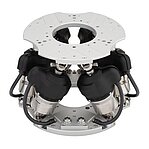
Hexapod Systems: Hexapod H-815 with C-887.3x/.4x Controller with Integrated Drivers for BLDC Motors
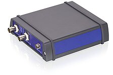
C-887 Hexapod Controller, Models C-887.3111, C-887.3511, C-887.4101, C-887.4111, C-887.4511
PI Simulation Models for CoppeliaSim / V-REP
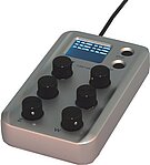
C-887.MC2 Manual Control Unit
EtherCAT Interface of C-887 Hexapod Controllers
Description of Coordinate Systems for Hexapod Microrobots and Parallel-Kinematic Positioners
Description of PIHexapodEmulator software
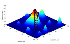
Fast Multi-Channel Photonics Alignment of Silicon Photonics Components with F-713 Alignment Systems and Hexapods from PI. PILightning Option for First Light Search
Motion of the Positioner. Position and Orientation in Space, Center of Rotation.
Product Description and Safety Instructions for Power Adapter C-501.24250D3W3
Ask for a free quote on quantities required, prices, and lead times or describe your desired modification.
6-axis controller for hexapods, integrated drivers for BLDC motors, TCP/IP, RS-232, 19" 2 RU housing, analog inputs
6-axis controller for hexapods, integrated drivers for BLDC motors, TCP/IP, RS-232, 19" 2 RU housing, EtherCAT interface, analog inputs
6-axis controller for hexapods, integrated drivers for BLDC motors, supports STO and SS1-t safety functions, TCP/IP, RS-232, 19" 2 RU housing
6-axis controller for hexapods, integrated drivers for BLDC motors, supports STO and SS1-t safety functions, TCP/IP, RS-232, 19" 2 RU housing, analog inputs
6-axis controller for hexapods, integrated drivers for BLDC motors, supports STO and SS1-t safety functions, TCP/IP, RS-232, 19" 2 RU housing, EtherCAT interface, analog inputs
Quickly receive an answer to your question by email or phone from a local PI sales engineer.
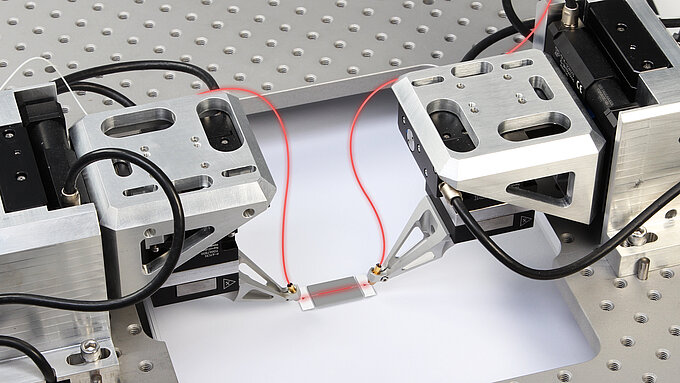
The need to align devices down to nanoscale accuracy is arising in many fields. Optical components such as the lenses or lens assemblies in small cameras, or even the CCD chip itself, need to be positioned with ever more precision.

Digital technology opens up possibilities for improving performance in control engineering which do not exist with conventional analog technology.
Fast USB or TCP/IP interfaces as well as RS-232 are the standard interfaces supported by modern digital controllers from PI. Furthermore, PI also provides digital or analog real-time capable interfaces.