High-Precision Spatial Positioning of Flat, Extended Objects

In a joint project, the ANKA (Angströmquelle Karlsruhe) at KIT (Karlsruhe Institute for Technology, Germany), the Fraunhofer IZFP (Institute for Non-destructive Testing Methods, Germany) Saarbrücken / Dresden, Germany, and the X-ray synchrotron source ESRF (European Synchrotron Radiation Facility, Grenoble, France) developed synchrotron laminography, which allows high-resolution 3D imaging on large flat objects. As an example the method is used for examination of composite materials used in wind turbines or in aerospace, for research on their inner structures before, during and after failure. The instrument has been in operation since 2007 at the Beamline ID19 of the ESRF. By means of so-called phase contrast methods it was also possible to successfully examine structures without absorption contrast. At ANKA, the newly commissioned IMAGE Beamline will provide the same method of analysis.
X-Ray Instrumentation: Maximum Demands on Stability and Precision
In laminography, the sample is scanned under rotation around an axis tilted with respect to the beam direction. The volume data can be reconstructed from the different projections. For this purpose, the sample is positioned between the X-ray source and the detector. The requirements are for utmost stability and precision in positioning both detector and sample in this inclined geometry. The repeatability of sample positioning following the beam reference measurement has been specified and measured at less than 0.5 μm. Rotation eccentricity also is less than 0.5 μm. This is important so that the various projection angles have the same projected rotation center. At lower accuracy, artefacts would occur during reconstruction.

Positioning Samples with Sub-Micrometer Accuracy
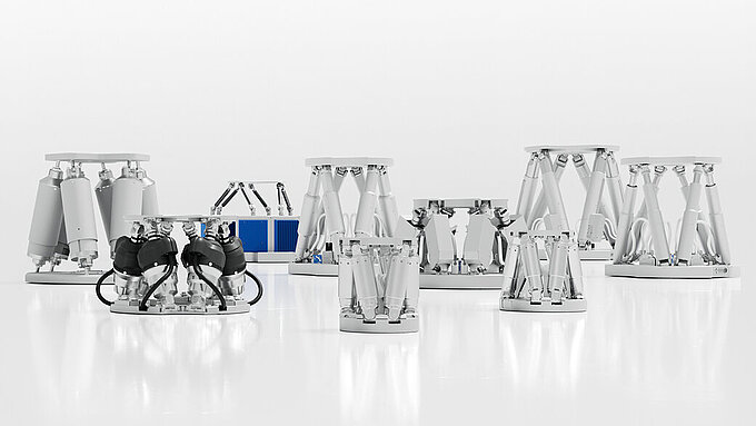
The angle at which the sample is rotated with respect to the synchrotron X-ray beam needs to be adjustable, while the lateral position of the sample itself allows the choice of the region of interest, securely and repeatably. The solution is a six-axis parallel-kinematic SpaceFAB underneath rotation and tilting stages on which the actual sample carrier is placed. Essential SpaceFAB features are the freely selectable pivot point and its high stiffness. The linear travel ranges are 150 mm × 150 mm × 50 mm, at 0.2 μm position resolution, ±12.5° tilting is possible for the axial angle, and ±5° for the other directions. Precision is provided by optical linear encoders and the high-precision mechanical components which are driven by a combination of stepper motors and ball screws.

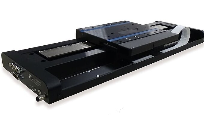
Above, a 360° rotating table enables 0.24 μm absolute flatness deviation only. The angle of the sample relative to the X-ray beam can be adjusted by up to 45° at a resolution of 0.001°. This design has a self-locking rack and pinion drive to remain stable during examination. The actual sample holder, an extremely thin frame carrier, is held magnetically, a flexure joint and air cushion provide optimal parallelism. Two linear stages shift and center the sample holder over 150 mm × 150 mm but do not touch it during operation.