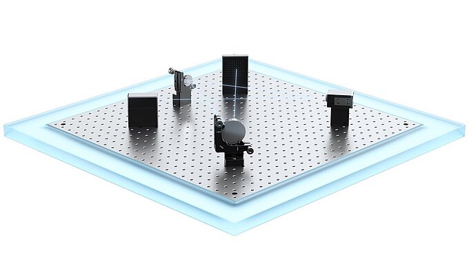

Piezo flexure tip/tilt platforms provide fast response, high resolution and stability - ideal prerequisites for fast steering mirror applications (FSM) and dynamic operation in scanning, tracking and image stabilizing. Since piezo motion is based on a solid state effects, piezo-driven systems and scanners can offer greater acceleration and dynamic bandwidth than voice coil or galvanometer scanners. When operated in closed-loop, piezo tip/tilt systems provided by PI can also achieve exceptional stability over long periods of time, for quasistatic positioning of optics with high demands on "pointing stability".
For highest guiding performance and life-time, flexure guides are used (Fig 1). Resolution into the nanoradian range are feasible along with high angular stability. Optical deflection angles of up to 70 mrad can be achieved with very short settling time (milliseconds to microseconds).
PI piezo tip/tilt systems are offered in single- and multi-axis versions. In addition, differential piezo tip/tilt systems are equipped with two piezo actuators per axis.
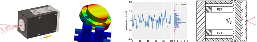
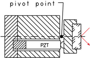
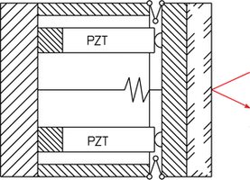
The design of a simple single axis system with a flexure guided tilt platform and one piezo actuator is shown in Fig. 1. The flexure forms the center of rotation (pivot point) and at the same time, preloads the piezo actuator. Simple design, low costs, and minimum space requirements are advantages of this version. A differential piezo drive is recommended for applications that require high angular stability over a wide temperature range.
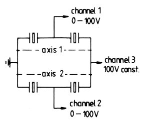
Actuators are operated electrically in a bridge circuit supplied with a fixed voltage and controlled by a variable voltage (see Fig 2 for schematic diagram of 2-axis tip/tilt platform.
The differential design allows the highest angular stability over a wide temperature range because the changes in temperature only affect one linear offset shift of the platform. Strain gauge sensors applied to the flexures or PZT actuators allow operation in closed-loop mode providing high linearity and excellent repeatability.
Multi-axis piezo tip/tilt systems are designed as parallel-kinematic systems (tripods or quattro pod) with all actuators acting on one platform. This design has great advantages compared stacked single axis systems. The motion platform is displaced only around one fixed center of rotation. Parallel-kinematic designs are well known from 6-DOF (degree of freedom) systems such as hexapods. Fig. 3b shows a high-speed, 6-axis motion system based on voice coil actuators.
A parallel-kinematic design reduces the moved mass (inertia) resulting in higher dynamics, compared to a mechanically stacked tip/tilt platform. The single pivot-point design also provides higher linearity and prevents the drawback of polarization rotation, which is common with conventional systems based on two individual single-axis galvo scanners operated sequentially.
For 3-axis applications a (Z-tip-tilt) a tripod design is used, as illustrated in Fig. 3a.
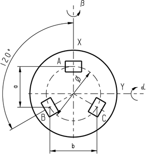

The multi-axis design in "tripod" form is driven by three piezo actuators arranged with gaps of 120° in between. The advantage of driving with three independent piezo actuators means that, in addition to tilting, the platform is also capable of liner motion which means, for example, that the controller can make use of optical phase differences (phase shift).
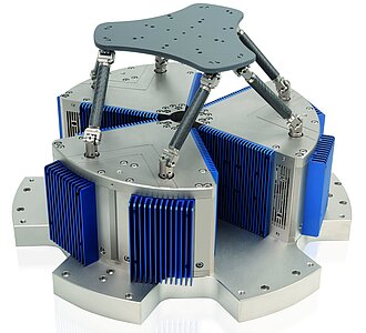
Fig 3b. A flexure-based, 6-axis parallel-kinematics motion platform. The struts of this high dynamics hexapod are driven by voice-coil motors. Systems like these 6-axis platforms are often used for camera shake and image stabilization algorithm testing.
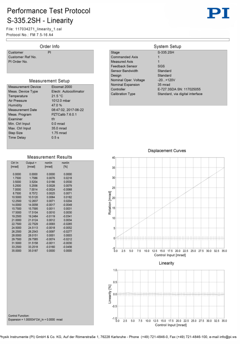
PI piezo flexure mechanisms are tested and calibrated using interferometers or autocollimators. Standard tuning provides the best overall performance in a wide range of applications. Custom system tuning can be tailored to match particular applications such as fastest settling with minimum overshoot and highest linearity for long travel ranges. A performance test sheet provides details on specifications such as linearity etc.
Some tip/tilt platforms come with a factory-installed mirror. For user-installed mirrors, guidelines in the manual should be followed. In any case, excessive force needs to be avoided; after all, these are precision mechanisms with nano-scale positioning capabilities. The mass of the mirror or optic mounted on the platform has an influence on the dynamic performance of the system. The greater the mass of the mirror or beam splitter mounted, the lower the resonant frequency and step & settle performance.
A centering tool (Fig. 5) and a 3-point template are recommended for handling mirrors and applying the adhesive. The template and the centering tool can be found here.
The template indicates the position the adhesive on the tip/tilt platform and restricts the quantity of the adhesive to be applied to avoid leakage inside the actuator housing. For best results, epoxy resin-based two-component adhesives with a hardening temperature of approx. 20 °C are recommended. Alternatively, PI can also mount the mirror as part of the order.
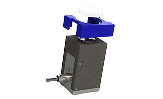
Fig. 5 S-335.2SH piezo tip/tilt system with 3-D printed centering tool (blue) for applying a 1-inch mirror (image: PI)
If the mirror has to be removed, PI recommends heating the mirror carefully with a hair dryer or hot-air gun to soften the adhesive. It should then be possible to remove the mirror easily.
Since the dynamic properties of the piezo tip/tilt system are related to the moment of inertia, changes to the load (inertia) may require an update of the servo control parameters in the piezo controller to guarantee the highest performance.
Analog and digital servo controllers are available for operation.
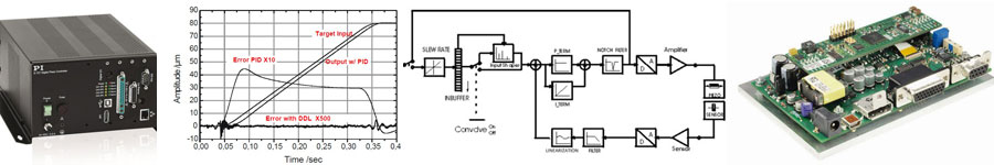
Digital servo controllers (Fig. 6) are recommended for most applications, especially when demands on the system performance vary, because retuning can be performed easily by software.
While analog servo controllers can provide cost benefits, they lack flexibility for remote tuning and the advantage of advanced algorithms with higher order error correction.
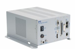
Fig. 6 E-727 digital servo controller / driver for multi-axis piezo flexure mechanisms. The latest version comes with an EtherCat interface for enhanced connectivity in industrial applications (Image: PI)
A graphic user program called PIMikroMove is available to update servo control parameters by simply pressing a button. An ID chip in the connector of the piezo tip/tilt system stores all factory calibration and tuning parameters and allows for a quick swap of controller and piezo mechanics in the field.
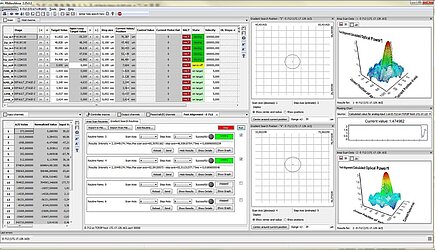
The PIMikroMove package also offers diagnostics tools and many functions and options for displaying important system data. PI also provides LabVIEW drivers and the entire control and measuring logic as a Dynamic Link Library (DLL) for easy integration into complex OEM systems.
5.2 PIMikroMove: Easy Configuration and Startup
PIMikroMove is an integral part of the extensive software package that is included in the scope of delivery of every digital PI controller. The software ensures easy and intuitive system startup.
In addition to position control commands, specification of step-size, and acceleration parameters, etc., a macro programming language can tie a string of single commences into continuous motion sequences.
Complex trajectories, should be programmed in the various high-level languages such as C, C++, C#, Python, LabVIEW as well as MATLAB and Simulink that are supported by PI.
Tuning and system analysis tools are also integrated to optimize and test each individual function of the system.
A data recorder can capture motion data during a move which can be displaced by a graphing tool for easy analysis.
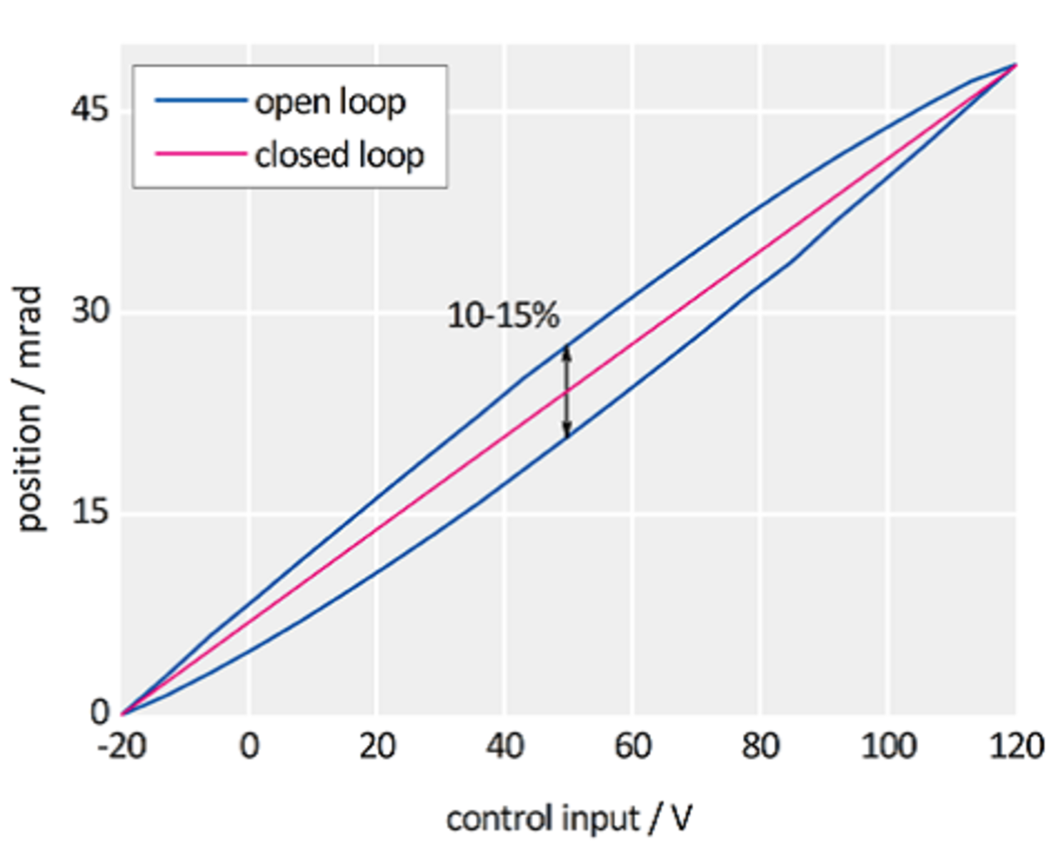
Piezo ceramic material expands quasi-proportional to the applied drive voltage. When run in open-loop (voltage control) mode, nonlinearity and hysteresis effects on the order of 10-15% are to be expected (Fig 7). Closed-loop piezo mechanisms are equipped with position sensors and are operated by a closed-loop servo controller that eliminates the nonlinearity and hysteresis effects, providing for higher accuracy and repeatability down to the nanoradian range.
6.2 Resonant Frequency
The dynamic properties of a piezo mechanism are related to its resonant frequency. The resonant frequency increases when the mechanical stiffness increases and drops when and moving mass is increased.
A rule of thumb is that the higher the resonant frequency, the higher the maximum operating frequency that can be achieved (the maximum operating frequency is usually significantly lower than the resonant frequency). In closed-loop operation, the maximum safe operating frequency is also limited by the phase margins of the system and a higher mechanical resonant frequency allows for a higher control bandwidth.
Resonant frequency of an ideal spring-mass system:
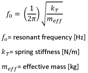
The above equation shows that in order to double the resonant frequency of a spring-mass system, either the stiffness must be increased by a factor of 4 or the effective mass reduced to 25 % of its original value.
For soft systems with heavy loads, dynamic operation is not possible.
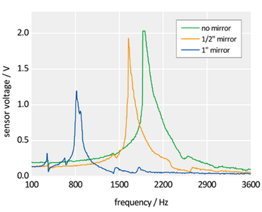
Fig. 8a shows the resonant frequency of an S-335 piezo steering mirror as a function of the mirror size.
Fast response is a beneficial characteristic of piezo mechanisms. A rapid change of the operating voltage causes a rapid change in the expansion (displacement) of the piezo ceramic actuator and therefore a change in the tip/tilt platform's position.
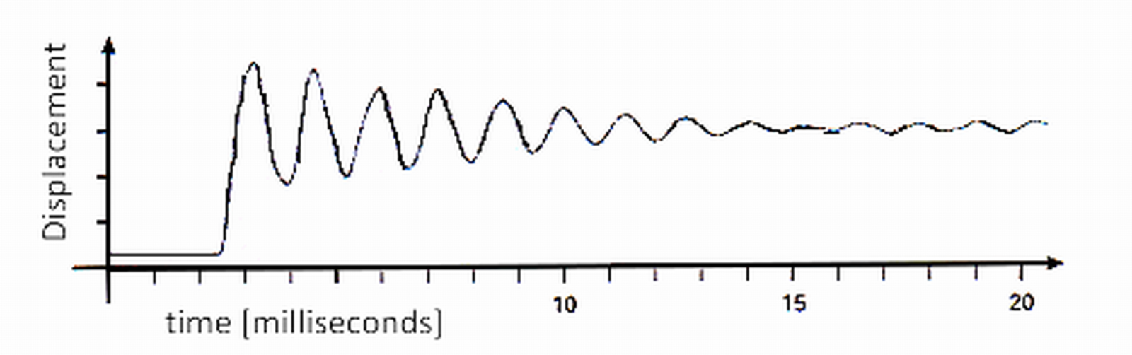
If the drive voltage increases rapidly, a piezo actuator can reach its nominal displacement in approx. 1/3 of the resonant frequency period (given the driver can provide enough current). In an open-loop system (or inappropriately tuned closed-loop system), such a rapid voltage change can induce overshoot and oscillations. (Fig. 8b)
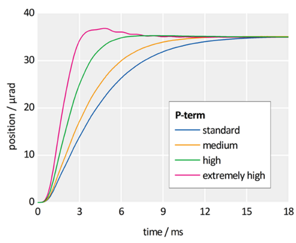
The influence of the P-term value on overshoot and step & settle performance of an S-335.2SH piezo tip/tilt system is shown in Fig 9.
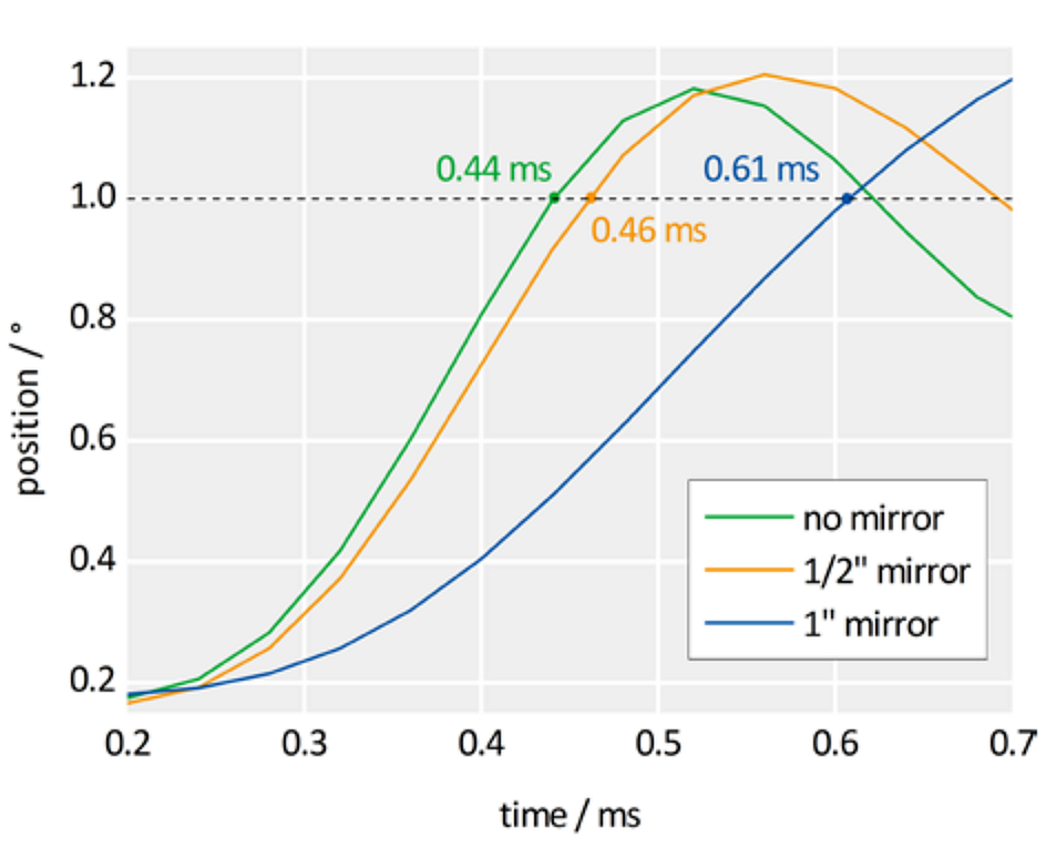
Fig. 10 depicts the influence of load / inertia (mirror size) on the settling performance.
The positioning repeatability depends on the displacement and the type of sensor employed in the system. Film or piezoresistive strain gauge sensors (SGS) are most often used in compact piezo mechanisms for their small size and low cost – they can be applied directly to the piezo actuators. With these analog sensors, the absolute repeatability improves with shorter displacement ranges. Residual errors result from the inferred position measurement and the strain gauge sensor technology itself. It would be beneficial to measure the platform angle directly, but for most applications it is either not possible (size) or the advantages do not warrant the additional expense.
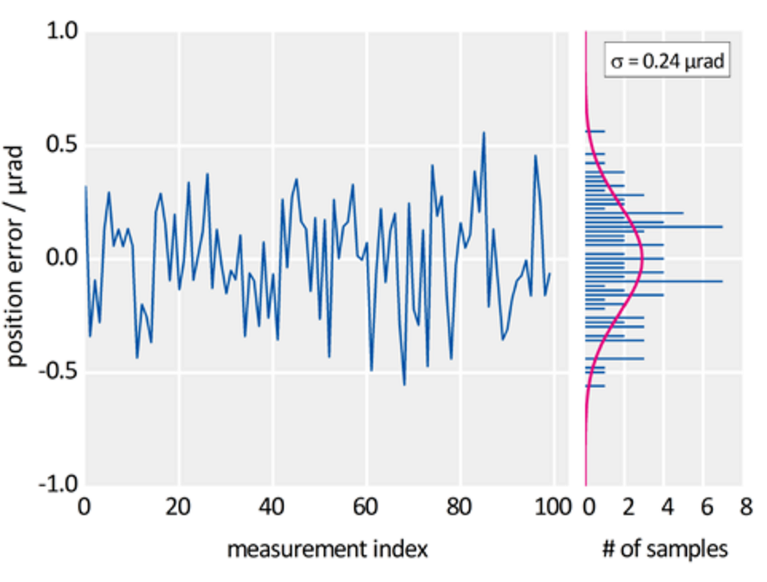
Repeatability performance can be measured with auto collimators or laser interferometers. Fig. 11 shows the typical S-335 repeatability performance graph based on 100 measurements (the deviation between the target and actual position is graphed as "position error") and the distribution in a histogram shown on the right.
6.4 Heat Generation During Continuous Operation
During long-term operation, heat generation can limit by the maximum operating frequency of the system. Because piezo actuators behave electrically similar to capacitive loads, their charge and discharge currents increase with the operating frequency. The drive voltage (equivalent to the angular displacement) has a quadratic influence on the power requirements and thermal loss.
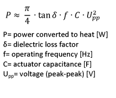
Due to the nonlinear, hysteretic properties of the piezo material, 8 to 12% of the electrical drive power put into the piezo actuators is lost as thermal energy. Therefore, cooling measures may be necessary at higher frequencies and amplitudes.
Fig. 12 shows the temperature rise over time of an S-331.2SL piezo tip/tilt system operated at 2000Hz (sine) with 100Vpp drive voltage (~70% max travel). The change of temperature was measured at the piezo ceramics.
In a closed-loop piezo positioning system the position creep known from open-loop piezo actuators is compensated by use of a position sensor and servo controller. Nevertheless, minimal position deviations can still be caused by temperature fluctuations. The use of differential piezo drives and sensors is recommended for optimum results.
6.6 Lifetime
Flexure guided piezo positioning systems provide very high reliability because of their frictionless, maintenance and wear-free characteristics of all included components. The lifetime of a well-designed piezo ceramic actuator is not subject to traditional mechanical wear of a standard actuator. Tests run by NASA/JPL have shown that PICMA® piezo actuators (the same types as used in all PI tip/tilt systems and piezo flexure nanopositioning stages) show no failures after 100 billion cycles. Because of the high performance, these multilayer actuators were selected for the Mars mission and integrated into an instrument on the Mars Rovers science lab.
Many years of careful design, testing and continuous improvements have lead to the extreme reliability of these monolithic piezo actuators. For example, the PICMA® piezo stack is covered entirely by a ceramic insulation layer that protects the actuators from humidity and failure resulting from increased leakage current, extending the lifetime considerably.
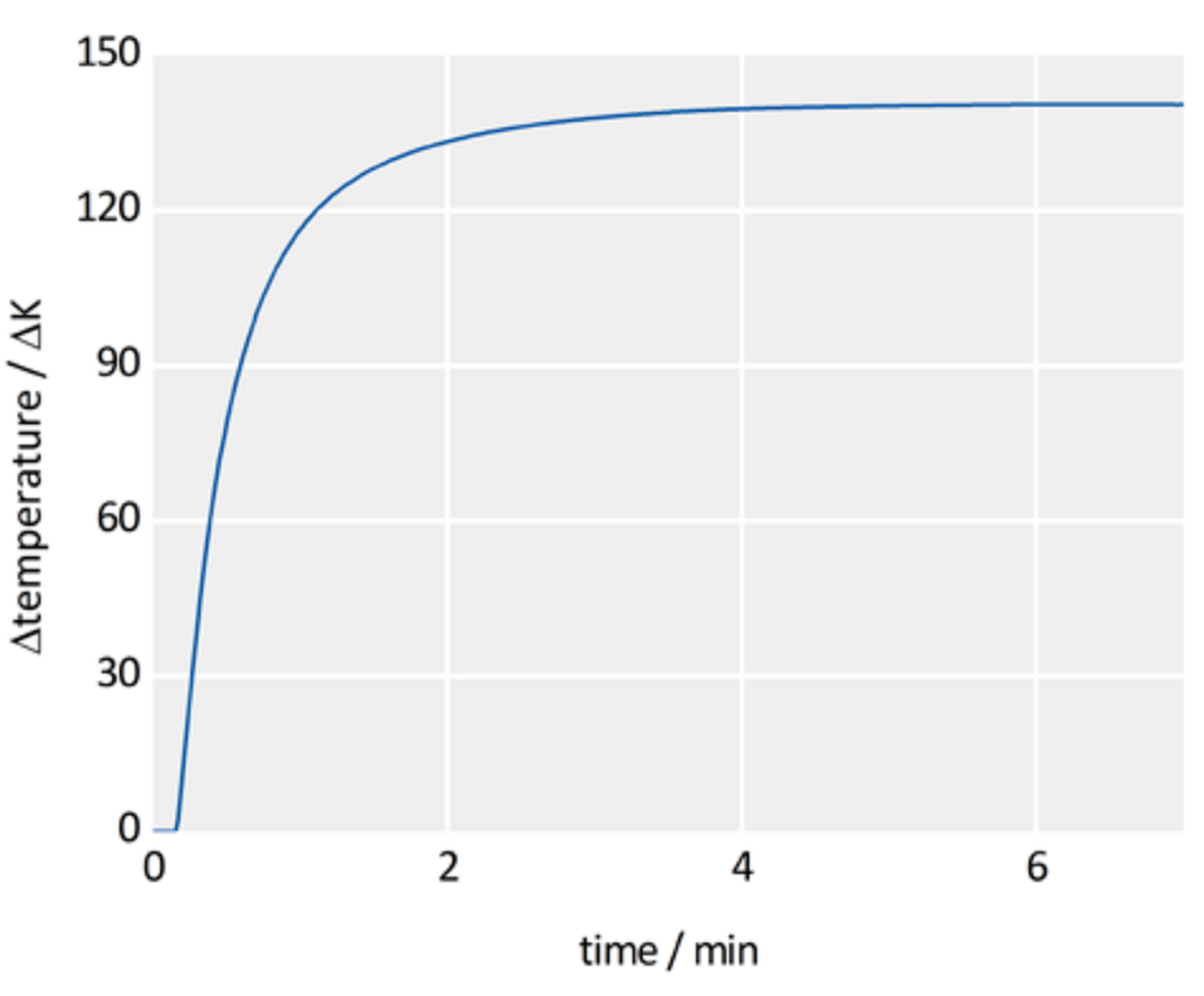
Micro-slots (Fig 13a) embedded in piezo stacks effectively prevent an excessive increase of mechanical tensile stress in the passive regions of the ceramics as well as uncontrolled expansion of micro cracks that would lead to dielectric breakdowns causing damage to the actuator.
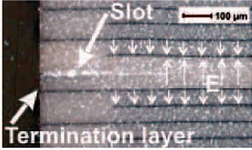
The meander-shaped design of the external contact strips ensures stable electrical contact to all inner electrodes, even under extreme dynamic loads with high currents (Fig. 13b).
7 OEM Engineering and Custom Solutions
PI has a long and successful history of working with customers on OEM solutions. Often it starts with a COTS (Commercial Off-The-Shelf) product. Small modifications can be achieved in a small time frame. Based on the large experience, design tools and standard modules available, our engineering teams can design custom solutions quickly.
Extensive testing and production equipment allow PI to react quickly to the development and production requirements of highly complex custom products and assemblies. All development procedures and production processes, from the initial idea to the final product, are controlled via a comprehensive management system.
All motion and positioning systems manufactured by PI undergo endurance testing with various load, operating and control conditions.
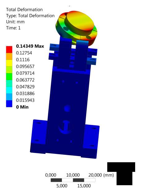
FEA (finite element analysis) tools are employed to optimize the performance and minimize material stress and potential for failure, ensuring high precision, and functionality before the first prototype is built.
Flexures, for example, which serve as guiding and preloading elements have a large optimization potential and our engineers are experts when it comes to flexure design. FEA helps find the best compromise between mass, size and stiffness, enhancing stability and reducing undesired creep effects.
Modal analysis during FEA optimization helps to reveal system resonances and other dynamic characteristics.
9 System Level Simulation
To gain insights into the overall system performance, parameters such as resonant frequency, damping, the electrical capacitance of the piezo actuators, servo control bandwidth etc. are used for a holistic simulation model. Based on these tools and extensive design experience, feasibility of customer requirements along with an early risk analysis can be performed quickly.
Author: Armin Karle is design engineer in the Piezo Systems R&D group at PI’s Headquarters.